Tuesday, 21 July 2015

Room to move

When we first moved into this place about seven years ago, I built some basic desks into my study/workshop. Well I keep expanding into unwanted parts of the house so it's time for some renovations. 
First some "before" shots! This was the work area in the old study, way too small to be useful and a huge bookshelf took up a 3m long wall.

Well both of those are gone and being replaced by proper kitchen cabinets giving me a short 1.5m x 650mm wide bench and a long 2.9m x 850mm wide bench with upper and lower cabinets!

As you can see it will make a huge difference. More to come.....


Wednesday, 24 June 2015

A microPLC..

In a moment of recent madness I said I would design a very very small programmable-logic-controller (PLC) for someone, including writing the language interpreter / byte code generator for it....

When will I learn!!!!

Hopefully the final product will run on something like the ATTINY84 or similar.

Defining the syntax rules

Portions of dodgy C

The byte code decompiler listing what the compiler produced.

Monday, 15 June 2015

Mini eBay monitor

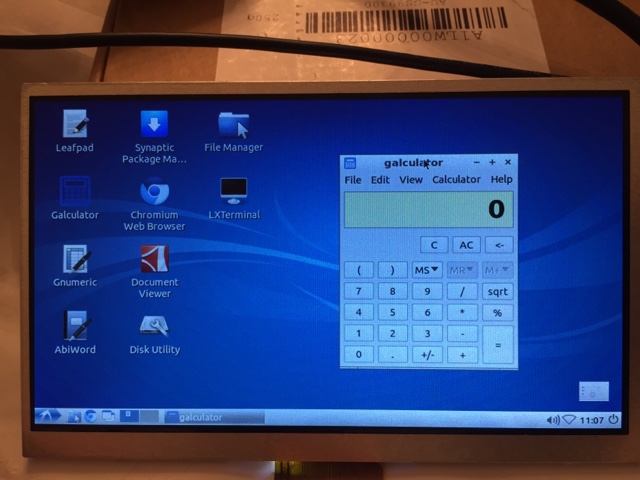
Last week I ordered a 7" HDMI/VGA/Composite monitor from an 'Australian' seller 'Globedealmark' for about $64 including postage. It comes as a bare PCB and LCD module with no documentation so they expect you to mount it in a case etc yourself.
Screen, controller and user controls
The board requires 12V DC at about 1amp. I first tried it on an old Windows 7 laptop using the VGA interface and a screen resolution of 1366x768 scaled automatically to the monitors native 800x480 pixels. It looks very good!
VGA input from laptop at 1366x768
Then I fired up the pcDuino Nano3 ARM board and tried that via HDMI. This time I set the resolution to match the display and the result is very nice.
Native 800x480 via HDMI
This is the combination I intend to use, mounted in a briefcase along with some SDR hardware. Altogether a good buy I think!
800x480
I forgot to mention that the display supports a reversed composite input for a car reversing camera etc too. Very hand all round.


Saturday, 6 June 2015

Airprobe-rtlsdr DC spike

HackRF with DC spike

I've been experimenting with the Airprobe-rtlsdr utility which is designed to demodulate non frequency hopping gsm signals and stream the demodulated data to Wireshark. Then in Wireshark you can use the built-in GSM decoding functions to extract cell tower identification etc. You CAN NOT decode the SMS or voice content so stop getting all excited!! That requires a whole lot more effort which would take you from the slightly illegal to the totally busted zone quick smart. Anyway when using the HackRF or it's clone the HackRF-Blue you face the usual large DC spike issue at 0Hz. This stops the demodulator from working so what I have done is add the GNU Radio DC blocker block to Airprobe-RTLSDR and now it (theoretically of course) decodes just fine.
Modifications to airprobe-rtlsdr.py

The modifications to the airprobe-rtlsdr.py file are shown in the above screen shot. I commented out the old code (three lines starting with #) and added the four new lines which insert the dc blocker into the signal chain. You also need to instantiate the dc blocker which is what is happening at the top of the image. Another thing not shown is that you must include the filter code from GNU radio so you need to add an import statement at the start of the code which says:
from gnuradio import filter

HackRF with DC spike removed

Monday, 27 April 2015

Up market SDR dev kits - AD9361

AD9361 SDR on AD-FMCOMMS2-EBZ
I'm lucky enough to have access to a range of different toys (err tools) and the latest gadget that someone has kindly lent me is an Analog Devices AD-FMCOMMS2-EBZ and a matching Digilent ZedBoard. This evaluation board features the AD9361 two channel 70-6000MHz SDR transceiver chip. The AD9361 has dual 12 bit ADC and DAC giving 72dB dynamic range (compared to the the HackRF's 48dB). Maximum bandwidth is 56MHz. The Ettus E310 is also based in this chip and that's a $4200 AUD radio. (about $2600 more than this solution)

Once of the best things about this evaluation kit is that Analog Devices fully support it and a number of different motherboards with a prebuilt Ubuntu ARM image which contains example applications and a fully functional GNU-RADIO source and sink block. This means you hit the ground running and you are not restricted to vendor specific applications. What will I do with it? Good question and hopefully I will be in a better position to answer it intelligently after I complete a week of FPGA/VHDL training next week :-) (Stay tuned for updates to this post)
Digilent ZedBoard ARM/FPGA combo.

Happiness is cheap connectors

I bit the bullet and trolled eBay for a reasonable dealer who offered a range of SMA connectors at sensible prices. I came across a store called av-rf who had a very good selection of connectors, adapters and ready made semi-rigid patch leads.
It has taken about two weeks for the order to arrive and for what they are the quality seems pretty decent. The bits and pieces in the photo came to under $50 AUD. There are four each SMA male-male, female-female, N-male-SMA-female, two BNC male to SMA female, four 15cm and four 30cm semi rigid patch leads, two SMA male to N male patch leads and not in the picture an SO239 to SMA.....

Sunday, 19 April 2015

Homebrew Discones


I need a broadband antenna for my SDR experiments, something that will cover 2M, 70cm and 23cm all in one would be nice. The discone seems like a reasonable general purpose omni-directional antenna with something resembling a 10:1 useable frequency range.


A bit of Googling and I came across an online calculator  so I used 140MHz as my lowest operating frequency (I had read somewhere that design figures can end up a bit short so start lower than you really want) and I came up with about 600mm for the cone sides and 428mm diameter for the top hat. I used copper coated steel TIG welding rods which are strong but also cheap and solderable. A tube of 28 2.4mm x 1m long rods was about AUD $19 from the local GasWeld store.

The eight radials forming the cone are soldered to a 15-20mm copper plumbing adapter, the inside of which is just right for sliding a bit of RG213 coax through. The top elements are soldered to a large washer. All a bit rough but this was only meant to be an experiment.

0-1400MHz sweep.
How did it sweep? Well, as you can see from the Rig Expert screen shot it's not as flat as I expected! The lowest usable frequency is about 152MHz where the VSWR is about 3:1 so really I should have designed it for about 130MHz and it may have come out usable on 2M (144-148MHz). 70cm and 23cm are fine. More experimenting required!! By the way I discovered these great heavy-duty microphone stands at Swamp in Fyshwick here in the ACT they are over 2m tall, very solid and well priced at $35 each. I also use them as speaker stands form a couple of studio monitors I have.

An update

I decided to build another Discone which would start a little lower so as to cover the airband. I also found the construction of the previous one a little fragile because I had soldered the ground radials to the outside of the copper fitting the coax passes through. So below is version two...
 
Discone version two - 120MHz up.

The top disc is again made up of copper coated steel welding rods, this time soldered to a brass disc. The overall diameter is 500mm. The ground radials are 694mm long and soldered into a gap formed by two copper plumbing fittings fitted together (see the pictures). This makes for a much more rigid assembly but the it could still do with a nice machined part to hold the disc and ground radials together. Now lots of photos which should be easy to follow.
Copper fittings. ID just right for RG213

Radials poked in gap
Soldered using 50/50 thick solder

Radials soldered into place.
RG213 fed through fitting ready to solder to top disc.

Top disc assembly
The resulting antenna has a frequency response very close to the design, the SWR drops sharply at 120MHz and they stays below 3:1 right up to about 1400MHz. I would have expected it to be a little flatter in places but perhaps their is some Discone matching black-magic I have not discovered yet. On air it seems to perform well.
This is the final frequency response of the new discone when swept from 1MHz to 3GHz. Quite usable on 2M (146MHz) up for transmit.


Saturday, 11 April 2015

New life for old filter - 2M LPF

Filter sweep 50-500MHz
Early last year I built some filters for a project I was involved in, today I dug out one that was labeled 350MHz LPF because I need a filter to go after the 250mW amplifier on the HackRF. I swept the filter and noted that it had a fair dip well before 350MHz so the label didn't really seem to fit. A little bit of trimming by spreading the turns of the inductors and tweaking the variable capacitor and I seem to have something good enough for 2M. Insertion loss looks to be about 0.5dB on 2M, down 19dB on the first harmonic and 48dB on the 3rd. That should be plenty to keep the HackRf / MGA31189 amp combo clean.

2M LPF

One thing about the sweep, this is on my rather old 23GHz spectrum analyser and 18GHz sweep generator, the two are not sync'd so I have set the sweep time on the generator to 60 seconds and left the analyser free running. The result is okay but nothing like using the modern Rigol DSA815 or the HP's I have access to... oh well.

Friday, 10 April 2015

We need more power Scotty!

Well +15dBm (~30mW) is all very good if you really enjoy true QRP but being as power mad as the next Canberrian I thought I would go all out and get myself a broadband linear for the HackRF. I wanted cheap and cheerful so for the moment I've settled on the MGA31189 based EME162 module from MiniKits. This kit is only AUD $24.70 without SMA connectors. Please ignore my very rough test leads in the photo!
MGA31189 +24dbM broadband driver
This kit is a +24dBm (250mW) broadband driver advertised as operating from 50MHz to 2GHz. You can build it - using supplied components - as a TX driver with onboard 5 or 10dB attenuator or as a second stage RX amp. I built mine with the 5dB input attenuator (right to left in the photo). Again a nice kit from Mark even if he accidentally forgot to include the 78M05 voltage regulator! A quick email and they will be in the mailbox soon enough. I already had some in the shack so it didn't slow me down.

Gain is quoted at about 21dB with a current draw of ~90mA. I only had time to do a very (very) quick test yesterday afternoon but the module looks very flat from about 70MHz to upwards of 2.6GHz. I got the following preliminary results with an input power of 2.75dBm (max on the HP generator) into the 5dB attenuator:
  • 50MHz 16dBm
  • 100MHz 18.2dBm
  • 150MHz 19.1dBm
  • 250MHz 19.3dBm
  • 438MHz 19.1dBm
  • 800MHz 18.9dBm
  • 1290MHz 18.7dBm
So that's very close to the stated 21dB of gain. More tests to follow.

HackRF - Spectral purity

An important thing to be aware of when using a wideband SDR like the HackRF or something like the Ettus E100 is RF spectral purity. How clean or dirty is the signal coming out of the SDR?

If you are running 30mW into an inefficient radiator or a dummy load for tests around the shack it probably doesn't matter a lot but as soon as you attach a decent antenna or amplifiers you'd better be sure you aren't stomping on parts of the spectrum you should'nt be.

Ettus E100 TX on 250MHz

I ran some basic tests on my HackRf recently using VK1XT's Rigol spectrum analyser, even out of the box it is pretty clean, I'd suggest it's probably better than the typical Baofeng (or similar) cheap eBay handheld and it is certainly cleaner than the much more expensive E100 I have used before. You can see the 1st harmonic at 500MHz is about -10dBc and the 3rd perhaps -22dBc on the E100.
HackRF on 2M


Transmitting on 144MHz on the HackRF you can see from the image that the 1st harmonic is about -35dBc and the 3rd is at -32dBc. (more to come).....

GNU Radio - python script startup delays

I've started playing with some Python scripts to control the HackRF and I found that it was taking a very long time to configure the device and to start transmitting in GNU Radio Python scripts. The time from invoking the script to the HackRf starting to transmit was almost a second (0.9s). A bit of experimenting led to an easy fix which has reduced the time to about 15mS!

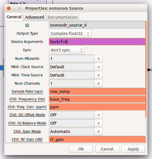
In the Python code generated by GNU Radio Companion there is a line where the Osmosdr driver is initialised, if you don't provide a device hint as a parameter to the driver it will go and search for all available devices supported by the driver, this takes quite a bit of time, but if you include the device hint the driver startup time is reduced dramatically.
Device hint in Python code

Device hint in GRC block
The same thing can be achieved in GNU Radio Companion by setting the device in the properties box for the Osmosdr source or sink block.

Now to continue developing some usable transceiver code :-)

RF switches from Minikits

Minikits RF Relay
Part of my plan to use the HackRF for amateur radio of course involves adding filtering and amplification. To switch things in and out of the transmit or receive signal path I needed some RF relays and I found just the thing at Minikits in the form of Mark's EME141 2.6GHz relay kit.

This kit comes in a couple of different forms, I elected to buy the version that includes female PCB mount SMA connectors for AUD $25.65 each.

The specifications say they are good from DC to 3.4GHz and the tests I have done tend to agree mostly with the figures on the site.
The quoted insertion loss and my measurements (which were almost identical on both boards I assembled today) are (NQ means not quoted on the site):
  • 145MHz, NQ, -0.18dB, isolation -55
  • 440MHz, NQ, -0.25dB, isolation -56
  • 1000MHz, NQ, -0.47dB, isolation -52
  • 1300MHz, -0.25dB, -0.49dB, isolation -50
  • 2000MHz -NQ, -0.9db, isolation -49
  • 2450MHz -0.2dB, -1.29dB, isolation -46
My measurements were done on a HP 25GHz spectrum analyser with inbuilt 3.5GHz tracking generator and semi-rigid silver SMA patch leads. There is a significant difference between the quoted insertion loss and what I measured at the higher frequencies so I'll redo that test some time.

The relay used on the switch is an OMRON G6Z-1F-A-DC5

Wednesday, 8 April 2015

Twinkle twinkle SDR

RF Chaos!
Just on two weeks ago I excitedly unpacked a parcel from SparkFun in the US. It was my first serious software defined radio (SDR), the HackRF One from Great Scott Gadgets. What a brilliant piece of gear for the price, even with the Australian sheckle being down on the USD it still comes in at less than AUD $400.

So, what do you get for your money?

Well, you get a little black plastic box with three SMA connectors on the ends and a mini-USB socket, along with a handful of LEDs. Actually you also get a suitable USB cable but that's about it.

Hidden in that unassuming box is a half-duplex transceiver capable of operating (officially) from 10MHz through to 6GHz, with an instantaneous bandwidth of 20MHz. Unofficially, it will cover essentially DC to 7.2GHz with a maximum bandwidth of around 21.5MHz but the performance will drop off as you venture to the far ends of this range.

Inside the HackRf One

Inside the box - which you open by loosening the three nuts on the SMA connectors and prying apart the edges with your fingernail - you will find a couple of expansion headers which give you access to various processor and I/O signals, the clearly defined RF section on the left and the large ARM processor on the right.

As I mentioned there are three SMA connectors mounted on the printed circuit board (PCB). The single connector on the same edge as the LED is the radio frequency (RF) in/out connector. This is the business end of the device where you would connect your antenna, amplifiers, filters etc. Note that these are standard SMA and not the reverse polarity SMA (RP-SMA) found on WiFi devices. If you connect a WiFi antenna with a RP-SMA connector to the HackRF the inner conductor of the cable will not actually be connected so be sure to use suitable adapters if you intend to use WiFi accessories on the HackRf.

On the other end of the board are two more SMA, these are clock-in (CLKIN) and clock-out (CLKOUT) connections which allow you to connect an external 10MHz frequency reference to the HackRF or to synchronise a second HackRF. The clocks signals are specified as 3.3V (maximum) square wave. Apparently the internal reference clock in the HackRF is automatically bypassed when you connect a suitable signal to the clock input. Using an external reference is completely optional as the on-board clock is already much more accurate and stable than that of a typical RTL-SDR TV dongle.

What can it do - I hear you ask! That would be a great question to ask if it were a normal radio transceiver like a UHF CB but being a software-defined radio the question is really what can't it do. Out of the box, it can't do anything. You need suitable software to make it do anything useful at all, luckily there are a number of applications available - almost free - to suit Windows, Linux, OSX and Android users.

Here are a couple of links to get you started:
  • SDR-Radio is an amazing Windows based application that supports the HackRF as well as a number of other SDR.
  • RF-Analyzer is an Android application which turns your Android phone or tablet into a fairly powerful handheld receiver / RF mapping tool.The RTL-SDR dongles are also supported.
  • GQRX provides OSX and Linux users with a nice multi-mode receiver.
  • GNU Radio is the single most powerful SDR tool available for Linux, OSX and Windows.
Using any of the above applications the HackRF becomes a quite capable multi-mode receiver capable of receiving SSB, AM, narrow-band (NBFM) and wide-band (WBFM) FM signals such as shortwave radio stations, CB, FM broadcast stations etc. If you want APCO25 (P25), DMR or D-STAR reception you really need to use GNU Radio with something like the examples available from VA3RFT/VE3IRR etc.

Transmitting on the HackRF is possible via GNU Radio or in a limited fashion using the command line utilities provided by the Linux drivers in the form of the hackrf_transfer command.

The hackrf_transfer command allows you to do a couple of things, it can generate a continuous unmodulated carrier on a specified frequency with adjustable output power or it can act as an RF record and playback utility. For example hackrf_transfer -r test.dat -s 8000000 -f 146000000 would record 4MHz of spectrum either side of 146MHz to a disk file called test.dat, this could then be played back again using hackrf_transfer -t test.dat -s 8000000 -f 146000000. A handy utility for taking RF snapshots for later analysis in GNU Radio or Baudline. The data file would contain interleaved 8 bit signed I & Q samples so two bytes of data per sample which turns into a lot of disk storage if left running for any significant length of time.

On the subject of 8 bits samples, this limits the HackRf to a dynamic range of 48dB (20log 2^8). Not as good as some higher end 12 or 16 bits SDR but perfectly adequate for the designed purpose of being a "hacking" SDR.

Anyway enough of an intro!